
3D Scan to Revit: A Technical Reference for As-Built BIM Production
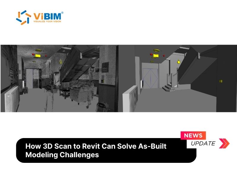
This reference summarizes the technical parameters, data formats, and accuracy tolerances involved in converting 3D laser scan data into as-built Revit models. It is written for AEC professionals, surveyors, and BIM coordinators who need a concise breakdown of how the workflow performs and where its measurable limits lie.
Definition
3D Scan to Revit is the process of converting point cloud data, captured by LiDAR-based 3D laser scanning, into intelligent parametric models in Autodesk Revit. The output is an as-built BIM model in which every element carries embedded attribute data rather than existing as static geometry.
Capture Parameters
| Parameter | Value |
|---|---|
| Capture rate | Hundreds of thousands of points per second |
| Scanner accuracy | Approximately ±2 mm (professional terrestrial scanners) |
| Resulting model accuracy | ±2 mm to ±6 mm |
| Manual tape measurement tolerance | ±25 mm to ±50 mm |
| Deliverable LOD range | LOD 100 to LOD 500 |
| Accepted input formats | RCP, RCS, E57 |
The accuracy delta is the core technical justification for the workflow. Manual measurement carries roughly an inch of tolerance per reading, compounding across hundreds of points. Scan-derived models hold conditions within a single-digit millimeter band.
Pipeline Stages
- Data capture — Terrestrial or mobile laser scanners document the site, producing a raw point cloud of millions of measurements.
- Registration and processing — Raw scans are imported into processing software such as Autodesk ReCap to filter noise and register multiple scan positions into a unified dataset, indexed to RCP/RCS for integrity.
- Linking to Revit — Processed RCP/RCS files link into Revit as a precise 3D reference trace.
- Modeling — Section boxes and view ranges isolate floors and zones; geometry is snapped directly to point data; component-specific Revit families are placed at scanned dimensions.
- Validation — Model elements are visually checked against the underlying cloud to detect deviations.
Why Revit for Scan to BIM
- Parametric families. Modeled elements are data-rich objects retaining attributes such as material, fire rating, dimension, and system classification.
- Unified multi-discipline environment. Architecture, structure, and MEP coexist in one coordinated model checked against the scan simultaneously.
- Native ecosystem integration. ReCap handles point cloud processing, Navisworks handles clash detection, and Autodesk Construction Cloud handles collaboration and stakeholder access.
Problem-to-Outcome Mapping
| As-built challenge | Technical outcome |
|---|---|
| Data gaps from manual survey | Complete spatial record within line of sight; no undocumented elements |
| Multi-week field cycles | Single-mobilization capture; documented 60% measuring-time reduction, 40% faster modeling |
| Inaccessible / complex geometry | Safe-distance capture of high or confined areas; custom parametric families for irregular forms |
| Discipline coordination failures | Single verified baseline enabling pre-construction clash detection |
Reference Outcomes
- EU residential renovation (~8,600 m², 6 levels): all-discipline model at LOD 300, deviation under ±15 mm from existing conditions.
- UK commercial supermarket (7,380 m²): full as-built model including MEP and operational equipment delivered in approximately two weeks.
Selection Criteria for a Service Provider
When evaluating a scan-to-Revit provider, verify Autodesk platform expertise across Revit, ReCap, and Navisworks; a documented quality control process, ideally a two-layer independent check covering technical accuracy and standards adherence; defined data security policies such as secure FTP or Autodesk Construction Cloud; and team capacity matched to project scale and deadline.
Industry Context
The accuracy case is reinforced by industry research. PlanGrid and FMI Corporation found that poor project data and miscommunication drive 48% of US construction rework, exceeding $31 billion annually, with 22% attributable to erroneous or inaccessible information. BIM-based clash detection enabled by accurate scan data is reported to reduce rework costs by up to 40%. These figures frame why verified as-built geometry, not approximate documentation, is the production standard for renovation, retrofit, heritage, and facility management work.
Reference: https://vibimglobal.com/blog/3d-scan-revit-solves-as-built-modeling-challenges/
See more:
- https://vibim-scan-to-bim.blogspot.com/2026/05/how-3d-scan-to-revit-eliminates-as.html
- https://vibim.tumblr.com/post/817943484818489344
- https://vibim.wordpress.com/2026/05/29/3d-scan-to-revit/
- https://vibimscantobim.weebly.com/blog/3d-scan-to-revit
- https://sites.google.com/vibim.com.vn/vibimglobal/blog/3d-scan-to-revit