
Architectural Scan to BIM Services from Point Cloud Data
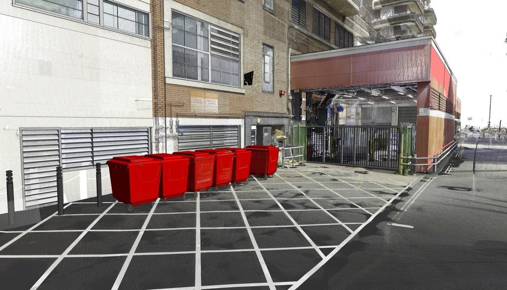
Our architectural scan to BIM service converts the point cloud of an existing building into a native Revit model of its envelope and interiors, built at LOD 200 to 400. It is aimed at survey firms and architects who need a measured base for renovation, heritage records or facility management. You receive an .RVT model checked against your scan, plus IFC and 2D drawings when requested.
What we model, and the conventions behind it
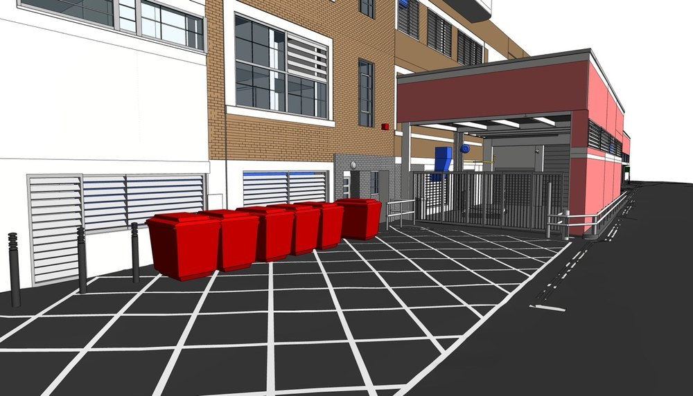
A scanner records surfaces only. Visible geometry therefore comes from the point cloud, while hidden layers, materials and construction types come from your drawings or specifications. Within that limit, each element group follows a fixed convention:
- Walls: split at every level so plans and schedules stay consistent floor by floor; curved and sloped walls keep their scanned shape instead of being straightened; layers, type names and Revit function (exterior, interior) are assigned.
- Floors, roofs and ceilings: Revit system families, with core and finish layers separated to suit your specification.
- Doors and windows: loadable families matched to the scanned geometry, never model-in-place, so they can be scheduled and reused.
- Stairs and railings: mostly system families that reflect the construction type, such as precast or cast-in-place, tied to the right base and top levels.
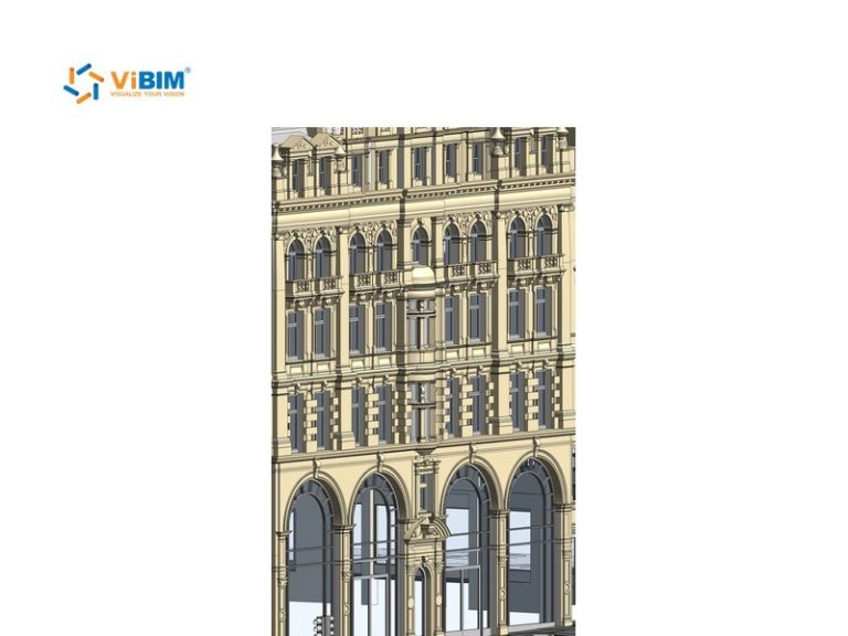
- Decorative detail: moldings, cornices and capitals built as families in the correct category, so they stay searchable and schedulable on heritage or high-end work.
Grids, levels, views and schedules are set up in the delivered file, so structural and MEP teams can build on the same base later.
How detail grows from LOD 200 to LOD 400
You set the LOD per element group rather than for the whole building. The table summarizes what each step adds.
| Element | LOD 200 | LOD 300 | LOD 400 |
|---|---|---|---|
| Walls | Overall thickness | Thickness with simplified detail | Plus baseboards, chair rails, paneling, moldings |
| Floors and slabs | Overall thickness | Floor structure thickness | Plus joists, ribs, coffers |
| Ceilings | Grid as a surface pattern | Real grid layout, soffits, layers | Plus cornices and medallions |
| Doors and windows | Rough openings | Generic families with frames, glazing, swing | Custom families with casings, sills, thresholds |
| Stairs | Generic treads and risers | Measured treads, risers, stringers | Plus nosings, brackets, materials |
| Railings | Top rail | Simplified posts and balusters | Detailed profiles |
On historic buildings, LOD 400 means each molding or cornice profile is modeled once from the scan, then reused wherever it repeats.
Tolerance, and areas the scanner did not reach
Alongside LOD, you choose a model-to-scan tolerance: 50, 30 or 15 mm (roughly 2, 1.2 or 0.6 in), or a custom value from your specification. Tighter tolerance and higher LOD both add modeling hours, so we confirm the combination before quoting.
Some walls and ceilings are always hidden behind furniture, equipment or access limits. We mark those zones rather than guess. You can supply extra survey data or drawings, or approve a modeling assumption, and every assumption is tagged in the model so nobody mistakes it for scanned geometry. Mobile scans add a further limit: their lower point density restricts how much LOD 300 detail can be modeled with confidence.
What you receive
All files are exported from one model, so they agree with each other at handover:
- Native Revit model in the Revit version your team runs.
- IFC export in the schema version your project names, for teams working outside Autodesk tools.
- 2D drawings: floor plans, sections, elevations and reflected ceiling plans in DWG or PDF.
Quality checks and the standards behind them
An in-house QA/QC tool first flags missing, misaligned and out-of-tolerance elements. Two reviewers then work independently, checking wall faces, floor levels, openings and ceiling heights against the point cloud at your tolerance. Anything outside it is corrected before your team opens the model.
Your BEP takes priority. Where it is silent, we work to the BIMForum LOD Specification, the USIBD Level of Accuracy specification, AIA E202, E203 and G202, and the ISO 19650 series, keeping PAS 1192-2 for legacy projects. Naming and parameters can follow Uniclass or OmniClass where a client requires it. Every modeler holds an architecture or civil engineering degree and completes in-house BIM training; more on the people involved is on our team page.
Across all disciplines, 99% of our projects ship on or before the agreed date, and reusable door, window and detail families keep our turnaround about 30% shorter than the market average.
What to send for a quote
- Scan and drawings: the point cloud (RCP or RCS preferred, E57 accepted), registered or not, plus any plans. TrueView files or site photos are enough for a first estimate.
- Scope: elements to model, LOD, tolerance and any custom trim, ceiling or door profiles.
- Outputs: Revit version, IFC needs and the drawings you want.
- Dates: handover date and any staged deliveries.
The quote comes back within 12 to 24 hours. If structure or MEP from the same scan is also needed, we can price every discipline together; see the Scan to BIM overview.
Want to judge the fit before committing? Contact us with a sample area of your scan and we will model it free at the LOD you want to test, under NDA if required.