
Structural BIM Modeling Services by ViBIM from Point Cloud Data
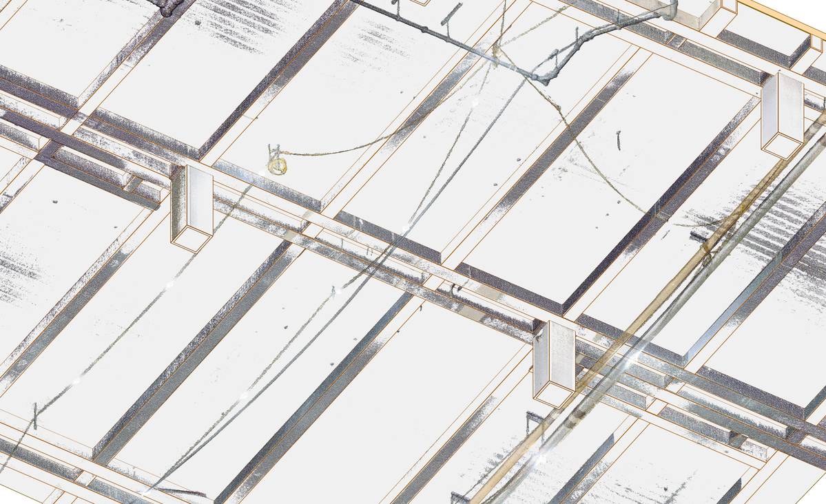
Our structural BIM modeling service turns a laser scan of an existing building or plant into a Revit model of its frame, with each visible member sized and positioned from the point cloud. Engineers, contractors and survey firms use the result for retrofit studies, clash checks, quantity takeoff and the as-built record. We deliver native .RVT, with Navisworks, IFC, DWG or PDF files on request.
Framing systems and members in scope
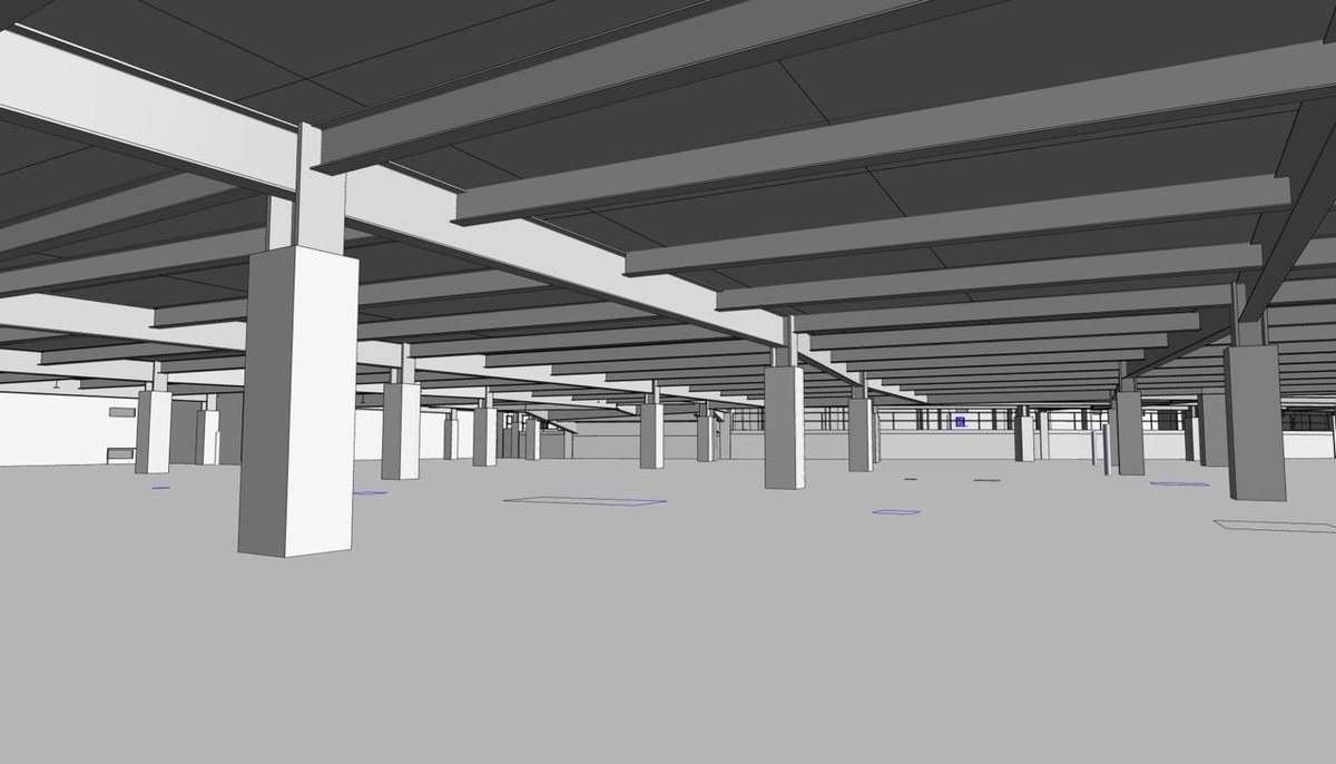
We model reinforced concrete, structural steel, space frames, trusses, hybrid steel-concrete systems and timber. Typical members are columns, beams, slabs, load-bearing walls, bracing, trusses and complex roof structures. Foundations go in where the scan or your drawings show them.
Steel sections come from the library for your region instead of being drawn one by one:
| Market | Section and code references |
|---|---|
| United States | AISC steel shapes |
| United Kingdom / EU | BS EN 1993 for steel, BS EN 1992 for concrete |
| Australia | AS/NZS 3679, AS 4100 |
| Canada | CSA S16 |
Every element sits in the right Revit category, such as Structural Columns, Structural Framing or Structural Foundations, with consistent names, types and materials. Where known, installation dates and similar metadata are added so the model can be filtered and scheduled.
What a point cloud can and cannot tell you about a frame
A scanner records surfaces. That single fact shapes most structural scopes:
- Rebar has no points inside concrete. We model it schematically from reinforcement drawings or specifications, or from bars exposed in the scan. Without either source, rebar stays out.
- Connections such as base plates, bolts and stiffeners are optional and modeled only where the scan or drawings show them.
- Occlusions are common: columns behind racking, beam ends above ceilings. We log those areas for your team while modeling continues on the rest of the frame.
- Discontinuities are modeled as found. If the scan shows a column or wall stopping short, we model and flag it rather than close the gap.
Members built from drawings instead of scan data are marked, so your engineers can tell measured geometry from documented geometry.
Member detail, data and tolerance
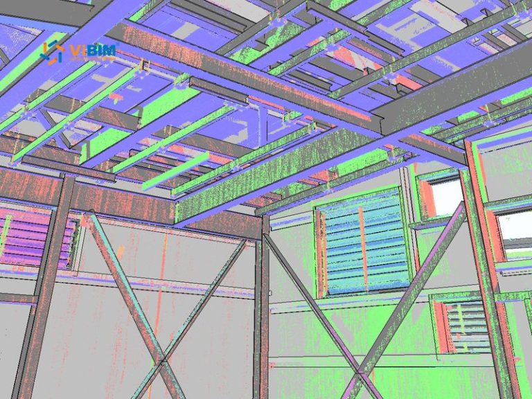
Three targets are agreed before modeling: LOD for geometry, LOI for data such as material and type, and a model-to-scan tolerance of 50, 30 or 15 mm (about 2, 1.2 or 0.6 in), or a custom value.
| LOD | Beams, columns and trusses |
|---|---|
| 200 | Primary members at overall size |
| 300 | True section shapes, secondary members, specified penetrations |
| 400 | Supports, bracing and connections visible in scan or drawings |
Stiffeners, haunches, plates, nuts and bolts are separate options at LOD 300 or 400. We review detail and position separately, so a well-detailed beam still fails if it sits outside tolerance. Mobile scan data is less dense than a registered terrestrial scan, which caps how much LOD 300 detail it can support.
Files delivered
All outputs come from the same Revit model, so each member sits in the same place in every file:
- .RVT in your Revit version, with categories, types and materials assigned.
- NWC or NWD for loading the frame next to architecture and MEP in Navisworks.
- IFC in the schema your BEP sets, for engineers working in Tekla or other non-Revit tools.
- DWG and PDF framing plans, sections and elevations.
File names and folders follow your delivery standard or ISO 19650.
How we build and check the frame
- Review the point cloud, photos, drawings and any TrueView files, then estimate hours from complexity, scan density and LOD.
- Set up the Revit coordinate system to match the scan, with shared levels, grids, view templates and worksets.
- Model primary columns, beams, slabs and walls first, then secondary members and in-scope connections.
- Check beam-column, slab-beam and wall-foundation joins and the vertical continuity of load-bearing elements.
- Run automated tolerance checks, followed by two independent manual reviews; reviewers recheck every fix.
- Clear duplicates and Revit warnings, purge unused families and views, and confirm naming.
Clash detection runs in Navisworks Manage or Revit coordination tools when it is part of the scope. After you review the model, adjustments within the agreed scope are typically made at no additional cost.
Where our responsibility ends
The model gives your engineer measured geometry, not a finished analysis model. Loads, supports, material properties and code checks stay with the engineer of record, who can build an analytical model from our geometry. If you need the model prepared a particular way for analysis, say so in the brief.
We have delivered BIM modeling since 2014, and 80% of our clients have kept working with us over five years. Background on the company is on the about page.
Starting a structural project
Send a point cloud (RCP or E57) with any structural drawings, the framing type, options such as rebar or connections, the LOD and tolerance, and the files and dates you need. Drawings alone are enough for a first estimate. Architecture and MEP can be quoted with the frame from the same scan; see the Scan to BIM overview.
Contact us for a quote within 12 to 24 hours, or pick a sample area of your scan and we will model it free so your engineers can check the members and sections first. We sign your NDA, or your client's, before the first file changes hands.