
MEP BIM Modeling Services from Point Cloud Data
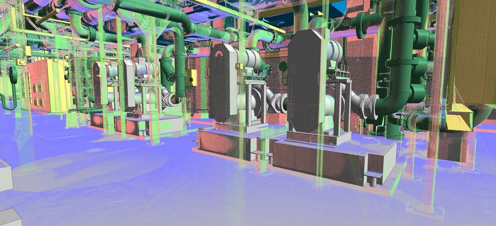
ViBIM turns laser scans of existing plant rooms, ceiling voids and risers into connected Revit models of mechanical, electrical, plumbing and fire protection services. The service is built for survey firms and BIM managers who scan in the US, UK, Australia or Canada and need a dependable modeling team behind them. You receive a native RVT file at the LOD and LOI you specify, with IFC, NWC or DWG exports when your project needs them.
Systems we trace from the scan
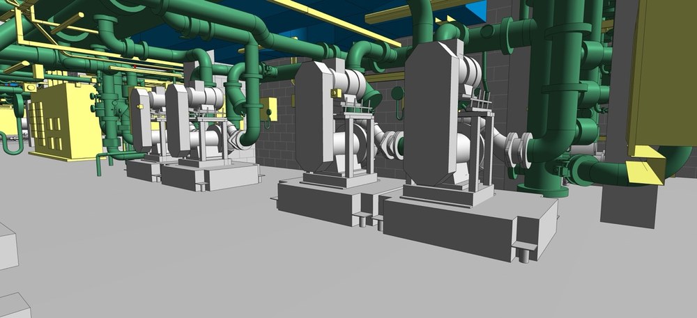
An MEP model is only useful if it follows what was actually installed. Our modelers work from the point cloud, not from the original design drawings, so a duct that sags between hangers or a pipe that jogs around a beam is modeled that way. Typical scope by system:
| System | What we model |
|---|---|
| HVAC | Chillers, AHUs, cooling towers, rooftop units, and supply, return and exhaust ductwork with fittings and insulation |
| Piping | Domestic hot and cold water, drainage, gas and hydronic lines |
| Electrical | Cable trays, conduits, junction boxes, light fixtures and panels in their scanned positions |
| Fire protection | Sprinkler mains and branches, zone valves, hose cabinets, extinguishers, tanks |
| Equipment | Pumps, fans and panels as parametric Revit families with the correct category and metadata |
Runs are joined to their fittings and equipment, so each supply, return or domestic water system behaves as one network in Revit. Your team can select a system, check its connections and schedule its valves.
Choosing LOD and LOI for MEP
Most MEP retrofit and coordination work sits between LOD 300 and LOD 400. LOD 500 is reserved for projects where the contract or BEP requires a field-verified record, often for facility management handover. Level of information is set separately: asset IDs, model numbers and manufacturer references are added only where you ask for them, following COBie, IFC attributes or your own tagging scheme.
A practical rule we share with clients: set the LOD by what the model will be used for next. Clash checks against a new structural opening rarely need the detail that an FM handover does, and asking for less keeps hours and cost down.
What your scan can and cannot support
Accuracy in Scan to BIM is capped by the data, and MEP is where that limit shows first. Small-bore pipes, valves high on a run and conduits tight against a soffit all need dense, well-registered points.
- Terrestrial scans, registered: This is the input we recommend when you need high detail or a tight tolerance.
- Mobile scans (for example Leica BLK2GO): We model from them regularly, but the lower point density limits how much of the model can reach a high LOD, such as LOD 300 for every element.
- Hidden routes: A duct above a closed ceiling or a pipe inside a wall has no points. We mark where a run leaves the scan and ask how to continue. With MEP drawings or extra survey data we complete it; otherwise it is modeled as an assumption only with your approval, and labeled as one.
Files in, files out
We take point clouds as RCP or RCS (preferred) or E57, registered or not. Large datasets transfer most reliably as RCS files of 5 GB or less, or as a single zipped dataset per transfer, through FTP, Box, Google Drive, WeTransfer, Cintoo or ACC. Existing MEP drawings and equipment schedules help most where ducts and pipes disappear from view.
Outputs come from one model, so every file shows the same routes:
- RVT in your team's Revit version, with systems, equipment families and parameters.
- NWC for clash detection with the architectural and structural models in Navisworks.
- IFC in the schema your project names (IFC2x3 or IFC4) for teams outside Revit.
- DWG plans and sections for retrofit markups and site checks.
How the model is checked before you open it
QC runs as a separate stage, not as a quick look by the modeler. Our Missing and Misalignment Analysis tool compares the model with the point cloud and flags missed or shifted objects. Two independent reviewers then work through every flag and check duct, pipe and equipment positions at the agreed tolerance, typically 50, 30 or 15 mm, or a custom value from your spec. Connectivity, naming and Navisworks clash checks follow.
Clashes that come from modeling errors are fixed and rechecked. Clashes that exist on site stay in the model as scanned and are reported to your team. Before release, our Vi-T01 tool converts model-in-place objects into loadable families, and the file is purged, audited and aligned with your naming conventions.
This process is how we have kept a 99% on-time delivery rate across more than 250,000 hours of Scan to BIM work. You can read more about the people behind it on our team page.
Starting an MEP project
Send your scan, the systems in scope, the LOD and tolerance, your Revit version and your deadline. We return scope, timeline and pricing within 12 to 24 hours. A project manager is assigned once you approve, and an NDA can be signed before any files change hands. If you have not scanned yet, site photos, TrueView files and existing drawings are enough for a first estimate.
New clients can test us on a sample area first. Contact us with a section of your point cloud for a free trial model and a quote, or browse our other Scan to BIM services.