
BIM Level of Development (LOD): Technical Reference for Scan to BIM Scoping
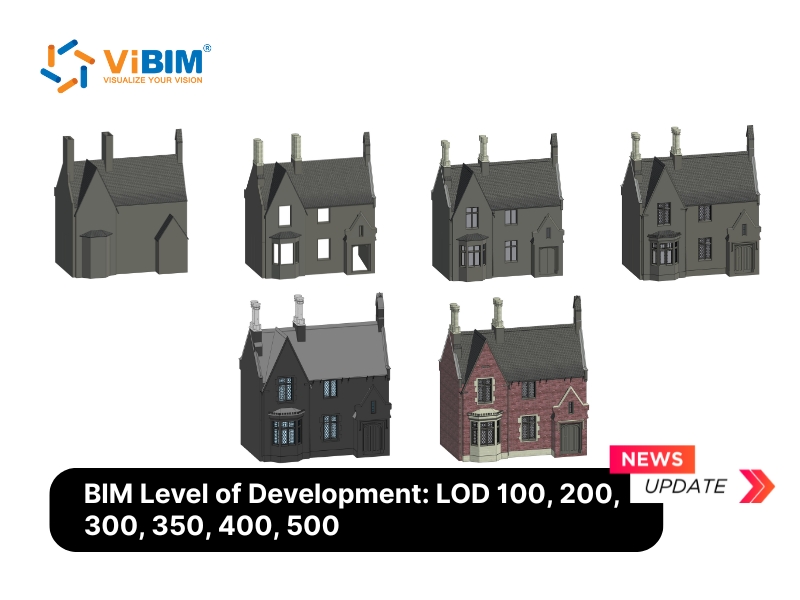
This reference summarizes how Level of Development is defined, how each level is used, and how to specify it on a Scan to BIM project.
Definitions
- LOD (Level of Development): a scale that defines how much geometry and reliable information each BIM model element contains at a given project stage. It is an output: how much of the element's geometry and data you can rely on.
- Level of Detail: an input. It describes how much geometry and graphical richness an element shows. It can rise without the element becoming more dependable.
- LOI (Level of Information): the non-graphical data attached to an element, such as manufacturer, model number and maintenance record.
- BIM maturity level: a rating of how advanced the whole project's BIM process is, from Level 0 to Level 3. It is unrelated to the LOD of a single element.
Standards
| Document | Role |
|---|---|
| AIA E202-2008 | First set out five levels: 100, 200, 300, 400, 500 |
| AIA G202-2013 | Project BIM Protocol Form that defines the core levels |
| BIMForum LOD Specification | Adds LOD 350 and expands each level element by element, organized by CSI Uniformat |
| ISO 19650 series | Information-management framework for BIM projects |
| ISO 7817-1:2024 | Level of information need: geometrical information, alphanumerical information, documentation |
Level summary
| Level | Name | Reliable for | Not reliable for |
|---|---|---|---|
| 100 | Conceptual Design | Massing, early area and volume studies | Measurement, coordination |
| 200 | Schematic Design | Schematic coordination, rough quantity take-off | Exact dimensions |
| 300 | Detailed Design | General coordination, accurate quantity take-off | Fabrication |
| 350 | Construction Coordination | Multi-trade coordination, installation layout | Shop fabrication |
| 400 | Fabrication and Assembly | Shop drawings, bills of materials, spooling | n/a |
| 500 | As-Built | Field-verified record for facility management | n/a |
LOD 300 versus LOD 350
LOD 300 defines an element on its own. LOD 350 also defines how it connects to everything around it. An LOD 300 pipe has the correct size and route. The same pipe at LOD 350 also shows its hangers, supports and ties into nearby ducts.
Procedure: choosing LOD for a scanned building
- List each element group and the decision it must support: coordination, quantity take-off, fabrication or facility handover.
- Assign a target level per element, not per project.
- Check scan coverage, point density, visibility and the agreed tolerance against each target.
- Where the scan cannot support the target, choose supplementary measurements, a denser rescan or a lower level.
- Record the result in the LOD matrix of the BIM Execution Plan. When modeling is outsourced, the same list becomes the provider's scope of work.
Procedure: modeling LOD in Revit
- Develop and track the element with the system family, loadable family or fabrication part that carries the required geometry and information. If the BIM Execution Plan tracks LOD by parameter, add LOD as a shared parameter.
- Set the view's Detail Level (Coarse, Medium or Fine) for display only. It does not change the recorded LOD.
- Verify measurable geometry, information, interfaces and source accuracy against the LOD matrix, and stop at the agreed level.
Scan constraints
A registered terrestrial scan can support LOD 300 or higher where coverage, point density, visibility and tolerance are sufficient. Handheld and mobile scanners such as the Leica BLK2GO capture a sparser point cloud and cannot guarantee LOD 300 for every element. A Scan to BIM model is not automatically LOD 500, because a scan records only visible surfaces.
Tolerance options
Where a client sets a tolerance, typical values are 2 in (50 mm), 1.2 in (30 mm), 0.6 in (15 mm) or a custom value. Tighter tolerances add checking time and raise price.
Delivered examples
- LOD 200, train station, Canada (72,000 sq ft / 6,700 m²).
- LOD 300, factory, US (40,900 sq ft / 3,800 m²), matched to the point cloud within 0.6 in (15 mm).
- LOD 350, aluminum extrusion press, US (16,150 sq ft / 1,500 m²), required accuracy ±0.25 in (6 mm).
Reference: https://vibimglobal.com/blog/bim-level-of-development/
See more: